
Short Circuits in Power Systems
A Practical Guide to IEC 60909-0
Inbunden, Engelska, 2018
1 499 kr
Tillfälligt slut
Reflecting the changes to the all-important short circuit calculations in three-phase power systems according to IEC 60909-0 standard, this new edition of the practical guide retains its proven and unique concept of explanations, calculations and real-life examples of short circuits in electrical networks. It has also been completely revised and expanded by 20% to include the standard-compliant prevention of short circuits in electrical networks for photovoltaics and wind energy. By understanding the theory any software allows users to perform all the necessary calculations with ease so they can work on the design and application of low- and high-voltage power systems. This book is a practitioner's guide intended for students, electrical engineers, engineers in power technology, the electrotechnical industry, engineering consultants, energy suppliers, chemical engineers and physicists in industry.
Produktinformation
- Utgivningsdatum2018-01-10
- Mått175 x 249 x 20 mm
- Vikt748 g
- FormatInbunden
- SpråkEngelska
- Antal sidor312
- Upplaga2
- FörlagWiley-VCH Verlag GmbH
- ISBN9783527341368
Tillhör följande kategorier
Hoppa över listan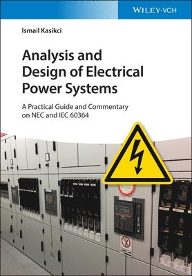

Mer från samma författare
Elektrotechnik für Architekten, Bauingenieure und Gebäudetechniker
Ismail Kasikci
Häftad, 2026
1 349 kr
Del 159
Del 148
Hoppa över listan
Du kanske också är intresserad av
Elektrotechnik für Architekten, Bauingenieure und Gebäudetechniker
Ismail Kasikci
Häftad, 2026
1 349 kr
Del 148
Del 159